"K40" Pour le K ? mais pour le 40 -> 40w est le nom souvent utilisé pour désigner sur internet une machine laser petit format pour graver et découper. On parle aussi de 3020 pour la base CNC de 30 cm x 20 cm qui correspond à la surface de travail. L'origine de la machine la Chine. L'interêt le prix et la possibilité illimitée de la modifier, mais aussi des surprises.
C'est partie j'ai commandé en chine sur Ebay sous la référence "CO2 LASER ENGRAVER ENGRAVING MACHINE 40W USB PORT CUTTER ARTWORK GOOD PRESTIGE" pour 436€ port compris mais attention aux frais de douanes Oufff pas pour moi..
J'ai commande aussi sur Ebay mon nouveau controleur ici : "Arduino Mega 2560 R3 + Ramps 1.4 + 3 endstop + LCD 12864 + 5 Pololu A4988 Stepper Driver For 3D Printer Reprap" 36€ surprise à la reception un vrai pas une copie.
Mes questions et mes doutes:
Quel controleur Arduino, Rasbery, smoothy, autres ?
Comment programmer Arduino ?
Avec quel firmware ?
Reglage des miroires ?
Comment on grave une image avec le laser ?
Réglage de la puissance du laser ?
Distance focale ???
Maintenant je suis en quête d'informations et mes sites cultes sont :
La référence le début.
http://3dprintzothar.blogspot.fr/2014/08/40-watt-chinese-co2-laser-upgrade-with.html
Une version correcte.
https://weistekengineering.com/?p=2464
http://www.cnczone.com/forums/general-laser-engraving-cutting-machine-discussion/256422-cnc-2.html
Le shema de l'alimentation...
http://smoothieware.org/blue-box-guide
Ici du lourd pleins de soucis...
http://wiki.labomedia.org/index.php/Lasercut
Réglages faisceau.
https://richardgrisafi.com/2014/10/10/setup-and-maintenance-of-a-40w-laser-cutter-from-ebay/
Configurations des Endstop
http://www.instructables.com/id/Configuring-Endstops-on-Ramps-14-with-Marlin-firmw/
http://solidutopia.com/fr/configurer-le-firmware-marlin/
Divers
http://fablabo.net/wiki/SmoothieBoard_Laser
https://inkscape.org/en/download/
Désolé pour les autres que je remercie au passage aussi mais la liste ne peut-être exhaustvie.
A la reception une grande joie, prix et délais corrects le tout dans un bel emballage.

A la mise en marche le tube laser ne fonctionne pas ?
Demontage ...


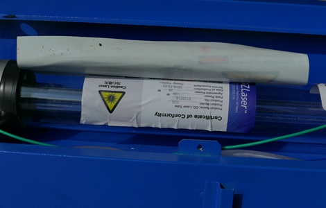
Aprés des recherches sur internet je ne suis pas le seul et la liste est longues. j'ai toujours espoir mais Oups le laser fourni par mon vendeur chinois acheté sur Ebay ...

Pour faire simple, la machine est équipée avec un controleur et une prise USB utilisation avec un Pc à travers les logiciels livrés CorelDraw + CorelLaser + LaserDRW et un Dongle. Cette suite logiciel est propriétaire et complexe voir peu fonctionnelle.
La précision des moteurs est nul et il sont bruyants. Le refroidissement du laser est dangereux.
Ici à droite la carte d'origine.

Donc le projet :
Remettre en fonction le LASER.
Nouvelle carte controleur.
2 Capteurs de température eau et laser.
Radiateur + pompe + ventillo.
Pointeur lumineux pour position laser.
Eclairage interne.
Boutons divers & bouton D'urgence
Capteur d'ouverture de capot.


Changer la carte interne d'origine une "m2Nano" par Arduino + Ramps 1.4 + écran LCD + bouton contrôle/reset + Lecteur SDHC et modification du panneau de commande. Programmation du nouveau controleur avec le firmware Marlin.


Pour la partie refroidissement liquide du laser un radiateur liquide + 2 ventillo 120 mm sur Aliexpress 25€.


La suite plus tard ..............


#ifndef CONFIGURATION_H
#define CONFIGURATION_H
#define STRING_VERSION_CONFIG_H __DATE__ " " __TIME__ // build date and time
#define STRING_CONFIG_H_AUTHOR "(none, default config)" // Who made the changes.
#define SERIAL_PORT 0
//#define BAUDRATE 250000
#define BAUDRATE 115200
#ifndef MOTHERBOARD
#define MOTHERBOARD 35
#endif
#define CUSTOM_MENDEL_NAME "Laser C System"
#define EXTRUDERS 1
#define POWER_SUPPLY 1
//============================= Laser Settings ==============================
#define LASER#define LASER_CONTROL 2
// Uncomment the following if your laser firing pin (not the PWM pin) for two pin control requires a HIGH signal to fire rather than a low (eg Red Sail M300 RS 3040)
#define LASER_FIRE_G1 10 // fire the laser on a G1 move, extinguish when the move ends
#define LASER_FIRE_SPINDLE 11 // fire the laser on M3, extinguish on M5
#define LASER_FIRE_E 12 // fire the laser when the E axis moves
//// Raster mode enables the laser to etch bitmap data at high speeds. Increases command buffer size substantially.
#define LASER_RASTER
#define LASER_MAX_RASTER_LINE 68 // maximum number of base64 encoded pixels per raster gcode command
#define LASER_RASTER_ASPECT_RATIO 1 // pixels aren't square on most displays, 1.33 == 4:3 aspect ratio
#define LASER_RASTER_MM_PER_PULSE 0.2 //Can be overridden by providing an R value in M649 command : M649 S17 B2 D0 R0.1 F4000
// Uncomment these options for the Buildlog.net laser cutter, and other similar models
#define CUSTOM_MENDEL_NAME "Laser Cutter"
#define LASER_WATTS 40.0
#define LASER_DIAMETER 0.1 // milimeters
#define LASER_PWM 50000 // hertz
#define LASER_FOCAL_HEIGHT 74.50 // z axis position at which the laser is focused
//=============================Thermal Settings ============================
//// Réglages capteurs de température:
// 8 is 100k NTC 3950 1% thermistor (4.7k pullup)
// changes made in ULTRA_LCD_IMPLEMENTATION_HITACHI_HD44780.H line 473 to allow temperature display
// instead of Z position, set to 1 for temperature, 0 for no temperature.
#define TEMP_SENSOR_0 8
#define TEMP_SENSOR_1 0
#define TEMP_SENSOR_2 0
#define TEMP_SENSOR_BED 0
// This makes temp sensor 1 a redundant sensor for sensor 0. If the temperatures difference between these sensors is to high the print will be aborted.
//#define TEMP_SENSOR_1_AS_REDUNDANT
#define MAX_REDUNDANT_TEMP_SENSOR_DIFF 10
// Actual temperature must be close to target for this long before M109 returns success
#define TEMP_RESIDENCY_TIME 10 // (seconds)
#define TEMP_HYSTERESIS 3 // (degC) range of +/- temperatures considered "close" to the target one
#define TEMP_WINDOW 1 // (degC) Window around target to start the residency timer x degC early.
// The minimal temperature defines the temperature below which the heater will not be enabled It is used
#define HEATER_0_MINTEMP -50
#define HEATER_1_MINTEMP -50
#define HEATER_2_MINTEMP -50
#define BED_MINTEMP -50
// When temperature exceeds max temp, your heater will be switched off.
#define HEATER_0_MAXTEMP 75
#define HEATER_1_MAXTEMP 75
#define HEATER_2_MAXTEMP 75
#define BED_MAXTEMP 75
// If your bed has low resistance e.g. .6 ohm and throws the fuse you can duty cycle it to reduce the
// average current. The value should be an integer and the heat bed will be turned on for 1 interval of
// HEATER_BED_DUTY_CYCLE_DIVIDER intervals.
//#define HEATER_BED_DUTY_CYCLE_DIVIDER 4
// PID settings:
// Comment the following line to disable PID and enable bang-bang.
#define PIDTEMP
#define BANG_MAX 255 // limits current to nozzle while in bang-bang mode; 255=full current
#define PID_MAX 255 // limits current to nozzle while PID is active (see PID_FUNCTIONAL_RANGE below); 255=full current
#ifdef PIDTEMP
//#define PID_DEBUG // Sends debug data to the serial port.
//#define PID_OPENLOOP 1 // Puts PID in open loop. M104/M140 sets the output power from 0 to PID_MAX
#define PID_FUNCTIONAL_RANGE 10 // If the temperature difference between the target temperature and the actual temperature
// is more then PID_FUNCTIONAL_RANGE then the PID will be shut off and the heater will be set to min/max.
#define PID_INTEGRAL_DRIVE_MAX 255 //limit for the integral term
#define K1 0.95 //smoothing factor within the PID
#define PID_dT ((16.0 * 8.0)/(F_CPU / 64.0 / 256.0)) //sampling period of the temperature routine
// If you are using a preconfigured hotend then you can use one of the value sets by uncommenting it
// Ultimaker
#define DEFAULT_Kp 22.2
#define DEFAULT_Ki 1.08
#define DEFAULT_Kd 114
#endif // PIDTEMP
#define MAX_BED_POWER 255 // limits duty cycle to bed; 255=full current
#ifdef PIDTEMPBED
//120v 250W silicone heater into 4mm borosilicate (MendelMax 1.5+)
//from FOPDT model - kp=.39 Tp=405 Tdead=66, Tc set to 79.2, aggressive factor of .15 (vs .1, 1, 10)
#define DEFAULT_bedKp 10.00
#define DEFAULT_bedKi .023
#define DEFAULT_bedKd 305.4
// FIND YOUR OWN: "M303 E-1 C8 S90" to run autotune on the bed at 90 degreesC for 8 cycles.
#endif // PIDTEMPBED
#define EXTRUDE_MINTEMP 170
#define EXTRUDE_MAXLENGTH (X_MAX_LENGTH+Y_MAX_LENGTH) //prevent extrusion of very large distances.
//============================= Mechanical Settings ===========================
// coarse Endstop Settings
#define ENDSTOPPULLUPS // Comment this out (using // at the start of the line) to disable the endstop pullup resistors
#ifndef ENDSTOPPULLUPS
// fine Enstop settings: Individual Pullups. will be ignored if ENDSTOPPULLUPS is defined
#define ENDSTOPPULLUP_XMAX
#define ENDSTOPPULLUP_YMAX
// #define ENDSTOPPULLUP_ZMAX
#define ENDSTOPPULLUP_XMIN
#define ENDSTOPPULLUP_YMIN
// #define ENDSTOPPULLUP_ZMIN
#endif
#ifdef ENDSTOPPULLUPS
#define ENDSTOPPULLUP_XMAX
#define ENDSTOPPULLUP_YMAX
#define ENDSTOPPULLUP_ZMAX
#define ENDSTOPPULLUP_XMIN
#define ENDSTOPPULLUP_YMIN
#define ENDSTOPPULLUP_ZMIN
#endif
//============================= ATTENTION INVERSION DES ENDSTOP X,Y MIN EN FALSE ===========================
const bool X_MIN_ENDSTOP_INVERTING = false; // set to true to invert the logic of the endstop.
const bool Y_MIN_ENDSTOP_INVERTING = false; // set to true to invert the logic of the endstop.
const bool Z_MIN_ENDSTOP_INVERTING = false; // set to true to invert the logic of the endstop.
const bool X_MAX_ENDSTOP_INVERTING = true; // set to true to invert the logic of the endstop.
const bool Y_MAX_ENDSTOP_INVERTING = true; // set to true to invert the logic of the endstop.
const bool Z_MAX_ENDSTOP_INVERTING = true; // set to true to invert the logic of the endstop.
//#define DISABLE_MAX_ENDSTOPS
//#define DISABLE_MIN_ENDSTOPS
// Disable max endstops for compatibility with endstop checking routine
#if defined(COREXY) && !defined(DISABLE_MAX_ENDSTOPS)
#define DISABLE_MAX_ENDSTOPS
#endif
//============================= INVERSION AXE ===========================
// For Inverting Stepper Enable Pins (Active Low) use 0, Non Inverting (Active High) use 1
#define X_ENABLE_ON 0
#define Y_ENABLE_ON 0
#define Z_ENABLE_ON 0
#define E_ENABLE_ON 0 // For all extruders
// Disables axis when it's not being used.
#define DISABLE_X false
#define DISABLE_Y false
#define DISABLE_Z true
#define DISABLE_E true // For all extruders
// For Z-Axis with leadscrews, uncomment to save homeing status when disabling steppers (axis is unlikely to move on its own)
#define Z_AXIS_IS_LEADSCREW
#define INVERT_X_DIR false // for Mendel set to false, for Orca set to true
#define INVERT_Y_DIR false // for Mendel set to true, for Orca set to false
#define INVERT_Z_DIR false // for Mendel set to false, for Orca set to true
#define INVERT_E0_DIR false // for direct drive extruder v9 set to true, for geared extruder set to false
#define INVERT_E1_DIR false // for direct drive extruder v9 set to true, for geared extruder set to false
#define INVERT_E2_DIR false // for direct drive extruder v9 set to true, for geared extruder set to false
// ENDSTOP SETTINGS:
// Sets direction of endstops when homing; 1=MAX, -1=MIN
#define X_HOME_DIR -1
#define Y_HOME_DIR -1
#define Z_HOME_DIR -1
#define min_software_endstops true // Si cela est vrai, l'axe ne se déplace pas à des coordonnées inférieures à HOME_POS.
#define max_software_endstops true // Si cela est vrai, l'axe ne peut se déplace à des coordonnées supérieures aux valeurs maxi définies ci-dessous.
// Travel limits after homing
// China Town K40 CO2 Laser Engraver/Cutter
#define X_MAX_POS 329
#define X_MIN_POS 0
#define Y_MAX_POS 228
#define Y_MIN_POS 0
#define Z_MAX_POS 75
#define Z_MIN_POS 0
#define X_MAX_LENGTH (X_MAX_POS - X_MIN_POS)
#define Y_MAX_LENGTH (Y_MAX_POS - Y_MIN_POS)
#define Z_MAX_LENGTH (Z_MAX_POS - Z_MIN_POS)
// The position of the homing switches
//#define MANUAL_HOME_POSITIONS // If defined, MANUAL_*_HOME_POS below will be used
//#define BED_CENTER_AT_0_0 // If defined, the center of the bed is at (X=0, Y=0)
//Manual homing switch locations:
// For deltabots this means top and center of the cartesian print volume.
#define MANUAL_X_HOME_POS 0
#define MANUAL_Y_HOME_POS 0
#define MANUAL_Z_HOME_POS 0
//#define MANUAL_Z_HOME_POS 402 // For delta: Distance between nozzle and print surface after homing.
//// MOVEMENT SETTINGS
#define NUM_AXIS 4 // The axis order in all axis related arrays is X, Y, Z, E
#define HOMING_FEEDRATE {30*60, 30*60, 0, 0} // set the homing speeds (mm/min)
// Lansing Makers Netowork Laser Cutter
#define DEFAULT_AXIS_STEPS_PER_UNIT {157.4802,157.4802,6047.2440} // default steps per unit for Ultimaker
#define DEFAULT_MAX_FEEDRATE {7600, 7600, 10, 25} // (mm/sec)
#define DEFAULT_MAX_ACCELERATION {2600,2600,2.5,2.5} // X, Y, Z, E maximum start speed for accelerated moves. E default values are good for skeinforge 40+, for older versions raise them a lot.
#define DEFAULT_ACCELERATION 2000 // X, Y, Z and E max acceleration in mm/s^2 for printing moves
#define DEFAULT_RETRACT_ACCELERATION 2000 // X, Y, Z and E max acceleration in mm/s^2 for retracts
// The speed change that does not require acceleration (i.e. the software might assume it can be done instantaneously)
#define DEFAULT_XYJERK 10.0 // (mm/sec)
#define DEFAULT_ZJERK 0.4 // (mm/sec)
#define DEFAULT_EJERK 5.0 // (mm/sec)
//=============================Additional Features===========================
#define EEPROM_SETTINGS
//to disable EEPROM Serial responses and decrease program space by ~1700 byte: comment this out:
// please keep turned on if you can.
#define EEPROM_CHITCHAT
// Preheat Constants
#define PLA_PREHEAT_HOTEND_TEMP 180
#define PLA_PREHEAT_HPB_TEMP 70
#define PLA_PREHEAT_FAN_SPEED 255 // Insert Value between 0 and 255
#define ABS_PREHEAT_HOTEND_TEMP 240
#define ABS_PREHEAT_HPB_TEMP 100
#define ABS_PREHEAT_FAN_SPEED 255 // Insert Value between 0 and 255
#define REPRAP_DISCOUNT_SMART_CONTROLLER
// ==> REMEMBER TO INSTALL U8glib to your ARDUINO library folder: http://code.google.com/p/u8glib/wiki/u8glib
#define REPRAP_DISCOUNT_FULL_GRAPHIC_SMART_CONTROLLER
//automatic expansion
#if defined (MAKRPANEL)
#define DOGLCD
#define SDSUPPORT
#define ULTIPANEL
#define NEWPANEL
#define DEFAULT_LCD_CONTRAST 16
#endif
#if defined (REPRAP_DISCOUNT_FULL_GRAPHIC_SMART_CONTROLLER)
#define DOGLCD
#define U8GLIB_ST7920
#define REPRAP_DISCOUNT_SMART_CONTROLLER
#endif
#if defined(ULTIMAKERCONTROLLER) || defined(REPRAP_DISCOUNT_SMART_CONTROLLER) || defined(G3D_PANEL)
#define ULTIPANEL
#define NEWPANEL
#endif
#if defined(REPRAPWORLD_KEYPAD)
#define NEWPANEL
#define ULTIPANEL
#endif
#if defined(RA_CONTROL_PANEL)
#define ULTIPANEL
#define NEWPANEL
#define LCD_I2C_TYPE_PCA8574
#define LCD_I2C_ADDRESS 0x27 // I2C Address of the port expander
#endif
//I2C PANELS
//#define LCD_I2C_SAINSMART_YWROBOT
#ifdef LCD_I2C_SAINSMART_YWROBOT
// This uses the LiquidCrystal_I2C library ( https://bitbucket.org/fmalpartida/new-liquidcrystal/wiki/Home )
// Make sure it is placed in the Arduino libraries directory.
#define LCD_I2C_TYPE_PCF8575
#define LCD_I2C_ADDRESS 0x27 // I2C Address of the port expander
#define NEWPANEL
#define ULTIPANEL
#endif
// PANELOLU2 LCD with status LEDs, separate encoder and click inputs
//#define LCD_I2C_PANELOLU2
#ifdef LCD_I2C_PANELOLU2
#define LCD_I2C_TYPE_MCP23017
#define LCD_I2C_ADDRESS 0x20 // I2C Address of the port expander
#define LCD_USE_I2C_BUZZER //comment out to disable buzzer on LCD
#define NEWPANEL
#define ULTIPANEL
#endif
// Panucatt VIKI LCD with status LEDs, integrated click & L/R/U/P buttons, separate encoder inputs
//#define LCD_I2C_VIKI
#ifdef LCD_I2C_VIKI
// This uses the LiquidTWI2 library v1.2.3 or later ( https://github.com/lincomatic/LiquidTWI2 )
// Make sure the LiquidTWI2 directory is placed in the Arduino or Sketchbook libraries subdirectory.
// Note: The pause/stop/resume LCD button pin should be connected to the Arduino
// BTN_ENC pin (or set BTN_ENC to -1 if not used)
#define LCD_I2C_TYPE_MCP23017
#define LCD_I2C_ADDRESS 0x20 // I2C Address of the port expander
#define LCD_USE_I2C_BUZZER //comment out to disable buzzer on LCD (requires LiquidTWI2 v1.2.3 or later)
#define NEWPANEL
#define ULTIPANEL
#endif
#ifdef ULTIPANEL
// #define NEWPANEL //enable this if you have a click-encoder panel
#define SDSUPPORT
#define ULTRA_LCD
#ifdef DOGLCD // Change number of lines to match the DOG graphic display
#define LCD_WIDTH 20
#define LCD_HEIGHT 5
#else
#define LCD_WIDTH 20
#define LCD_HEIGHT 4
#endif
#else //no panel but just lcd
#ifdef ULTRA_LCD
#ifdef DOGLCD // Change number of lines to match the 128x64 graphics display
#define LCD_WIDTH 20
#define LCD_HEIGHT 5
#else
#define LCD_WIDTH 16
#define LCD_HEIGHT 2
#endif
#endif
#endif
// default LCD contrast for dogm-like LCD displays
#ifdef DOGLCD
# ifndef DEFAULT_LCD_CONTRAST
# define DEFAULT_LCD_CONTRAST 16
# endif
#endif
// Increase the FAN pwm frequency. Removes the PWM noise but increases heating in the FET/Arduino
//#define FAST_PWM_FAN
// Use software PWM to drive the fan, as for the heaters. This uses a very low frequency
// which is not ass annoying as with the hardware PWM. On the other hand, if this frequency
// is too low, you should also increment SOFT_PWM_SCALE.
//#define FAN_SOFT_PWM
// Incrementing this by 1 will double the software PWM frequency,
// affecting heaters, and the fan if FAN_SOFT_PWM is enabled.
// However, control resolution will be halved for each increment;
// at zero value, there are 128 effective control positions.
#define SOFT_PWM_SCALE 0
/*********************************************************************\
* R/C SERVO support
* Sponsored by TrinityLabs, Reworked by codexmas
**********************************************************************/
// Number of servos
//
// If you select a configuration below, this will receive a default value and does not need to be set manually
// set it manually if you have more servos than extruders and wish to manually control some
// leaving it undefined or defining as 0 will disable the servo subsystem
// If unsure, leave commented / disabled
//
//#define NUM_SERVOS 3 // Servo index starts with 0 for M280 command
// Servo Endstops
//
// This allows for servo actuated endstops, primary usage is for the Z Axis to eliminate calibration or bed height changes.
// Use M206 command to correct for switch height offset to actual nozzle height. Store that setting with M500.
//
//#define SERVO_ENDSTOPS {-1, -1, 0} // Servo index for X, Y, Z. Disable with -1
//#define SERVO_ENDSTOP_ANGLES {0,0, 0,0, 70,0} // X,Y,Z Axis Extend and Retract angles
#include "Configuration_adv.h"
#include "thermistortables.h"
#endif //__CONFIGURATION_H